McIntosh Model 30
restoration Journal:
Please excuse the poor
image quality of the pictures on this page, they were taken with a household-grade
camcorder, and an ATI video capture board, instead of a real digital camera!
September 23, 2001:
This is the latest
restoration project I am getting into. I am not only doing this to help
out a good friend, but to perserve a piece of electronic and technology
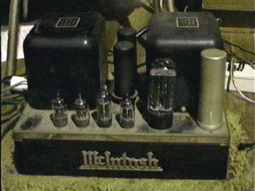
history. There are two amplifiers in this set. you are looking
at one of them here, covered in a thin layer of dust and corossion after
being stored in a damp basement for several years. You can see two
places on the top plate, on the far left end, and between the rectifier
tube (the largest one) and the main filter capacitor where I rubbed the
dust away with my fingers, and was able to produce a reasonable shine out
of the chrome-plated chassis. This entire chassis will eventually
get buffed to a bright shine. The glass tubes you see in the picture
are made by various manufactures. They were cleaned up with
glass-plus, and placed on a tube tester. There are also two
metal tubes(the black cans) in the back sitting between the two transformers
(the black boxes). These are military-grade RCA final output tubes.
There were no OEM McIntosh tubes found in either amp. While
none of the tubes are audiophile grade tubes, they certainly sounded great
upon powerup, and a test-play with Pink Floyd's "Dark Side of the Moon"
CD, and a set of Cerwinn-Vega CV12 speakers. Hum was barely
detected at the outputs, at less than .01 without a load attached to the
output...so it seems like our power supply componets are certainly in good
shape! One of the amps had a blown 3 amp power supply fuse, and was replaced.
One problem that did
occur though is that after about approximatley 30 minutes or so was the
amp that had the blown fuse blew it again! This was done very quietly
without any fanfare or sparks, which means a resistor could maybe be out
of tolerance (rare for carbon resistors), or a capacitor could be leaky.
This is very possible if these units have paper capacitors inside...a very
common componet of these days. It is a 3 amp fuse though, and the
spec's on the outside say that the amp is not supposed to pull more than
130 watts off the AC line. 3 amps is much more than that...360 watts
to be exact...so something is definitely not right!
September 30, 2001
After arriving back
from the Rescue Squad competitions in VA beach, I decided to take the bottom
plate off the amps and take a look around, and this is what I saw:
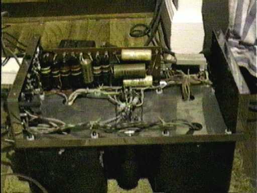
A rather nicely laid
out undercarrage with neatly tied back wiring. This is the amp that was
blowing fuses. A vertical card holds a multitude of...yep,
paper capacitors...and carbon reisistors. From this view, you are looking
at 10 paper capacitors mounted on the circuit board. The black, color-coded
pieces are acutally capacitors, not resistors. MacIntosh used the
better (for the time) bakelite coated ones. A check with the multimeter
reveals that several of these capacitors are in fact getting leaky.
I want to replace the entire set of paper/plastic capaictors with modern
ceramic capacitors, which should last indefinitely, and give excellent
tonal quality.
I did not find
a schematic underneath the chassis cover, which is frequently common on
units of this vintage, but due to the simplicity of these units, and the
excellent craftsmanship in laying out the chassis, componet replacment
ought to be rather easy. Because these are audiophile grade units,
whatever is done to one amp, will also need to be done to the other, even
if the componet is still good. This is so tonal quality will be simliar
between the two units. Not only will the componets be replaced in pairs,
but pairs of componets that will be used, will be checked with a meter
to find the closest matches.
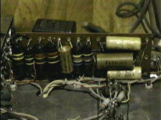
A closer view of the
capacitiors mounted on the board (yes, these are all cap's)
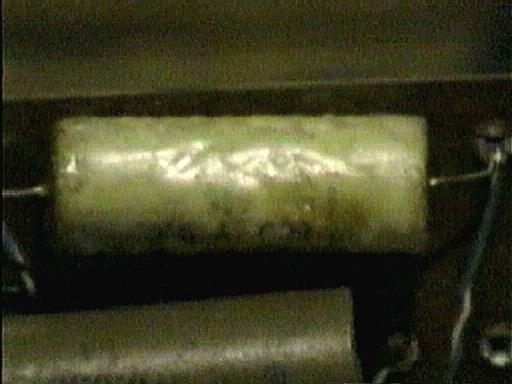
An extreme close-up
of a suspected bad capacitor. Notice the outer wax covering has melted
from leaking current, and getting hot. Capacitors should be cool
to the touch, even after extended playing. Unless they are leaky,
capaicitors typically do not produce any heat on their own.
General Information on the amplifiers:
The McIntosh model
30 amplifier is an audiophile grade monoural amplifier producing approximatley
30 watts RMS into a 4, 8, 0r 16 ohm load. Impedance can be matched
by simply connecting the speaker load to the proper screw terminal on the
output bar. Input impedance is a standard 600 ohm, 500 millivolt
"line level" with adjustable gain via a control knob. The beauty
of these amplifiers is not in what they contain, but on what they DON'T
have. What I mean by this is that these amplifiers were engineered
to have as few componets in the signal path as possible. This minimizes
distortion and coloration of the sound...A concept that many electronic
engineers have seem to forgotten in new equipment!
VACUUM TUBE LIST:
6L6: final audio output
5U4: power supply
recitifer
12AX7: phase inverter
12AX7: input buffer/
input preamp
12AU7: secondary
12BH7: teritary