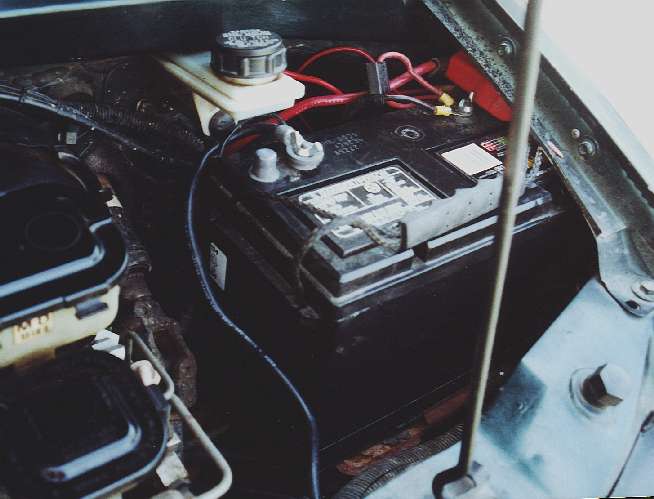
A group 27 battery installed, note it's backwords from OEM, and the way the side-post terminals are attached.
DEEP-CYCLE BATTERY:
Since the late 70's GM has
used side-terminal batteries, which has hindered users from installing
any old battery. This is true in the Astro's as well. I have
found out that the Delco Voyager, or any group size 27 battery actually
fits quite nicely in this van though! The battery needs to be installed
backwords from it's OEM postion, and the cables routed slightly differrently.
This configuration will place the positive lead on the right side, under
the fender, and the negative on the left, beside the brake master cylinder.
On most Deep-cycle batteries, they have screw terminals, along witht the
posts. Just simply take the screw out of your battery cable so there's
a hole in the middle, and place on the screw terminal of the battery, and
tighten the screw...it's that easy! If you plan to use the screw
terminals from other accessories, you can buy the top to side terminal
converters, they work quite nicely too. I recommend using the side
post converters which will leave the screw terminals open. This will also
allow you to jumpstart easily.
Warning:
If you replace your power cable to your starter when you do this, like
I did, Make sure the little pigtail wire going from the battery terminal
to the fusebox is large enough! This little pigtail handles all the
"accessory" draw on the vehicle, such as lights, AC, radio, ECM, and any
other thing electrical on the van but the ignition system. The EXIDE
cable that I bought only had a 12 gauge wire and was not enough to carry
all the power this van will draw, it needs at least an 8 gauge wire or
larger! If it's too small, this wire will melt, burn out, and leave
you with EVERYTHING in your vehicle DEAD!!!!
A group 27 battery installed, note it's backwords from OEM, and the
way the side-post terminals are attached.
SPLIT ELECTRICAL SYSTEM:
Well, mine is not quite fully split...yet!
To have a fully split electrical system, you need not only two separate
batteries, but two separate circuits. I only have the latter.
There is simply no more room under the hood of the Astro for additional
batteries. The biggest advantage of wiring up your electrial
system like this is that you do not need to break into the OEM stuff hardly
at all. This can save quite a lot of headaches since you don't need
to mess with stuff that's already working!
The way I wired the split electrical system was to pull a 6 gauge line off the battery to a separate fuse / relay board underneath the driver's side seat. From there, power is distributed to all the toys I've added, like the Stereo amp, neon interior lamps, 2 way radios, fog lights, etc. I got a switchbox that was intended to go into a police car, and hooked up to the relay board that comes with the Whelen light bar/siren kit. Instead I made my own relay board out of old Ford starter solenoids(being resourceful here!). Relays are simply an electrically operated switch (sounds like a solar powered flashlight doesn't it!) A relay is useful because it takes only a small amount of electricity to activate one, and switch on a large amount of current, like what a stereo amp would draw.
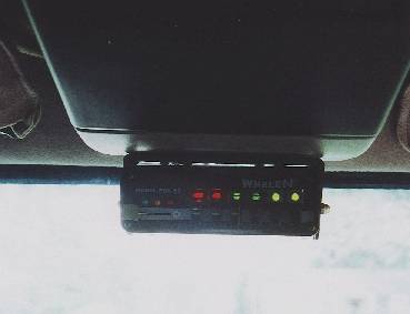
The switchbox installed at the front edge of the ceiling console.
The reason for relays
is because I can use much smaller switches, wiring, and other hardware.
It is also safer, since the switchbox is on it's own 2 amp circuit, there
is little chance this little bit of current will cause any serious damage
if something were to fail. It is these low current lines that are running
around behind trim panels, headliners, etc. If the switchbox
were to fail, all the circuits would shut down, not just the switchbox.
Another advantage is you can keep your high-current power lines as short
as possible. This is important because voltage drop is problem at
only 12 volts.
The heavy current
handling is done by the relays, on a board under the seat. The relays
are basically Ford Starter solenoids. All the parts you see in the
picture below can be had from scrap. The relays came out of old Ford
cars, the wiring, connectors, and fuse blocks out of an old Burroughs mainframe
computer. The piece of wood was scrap from a friend's sailboat project,
and the switchbox pictured above came out of an old rescue squad car.
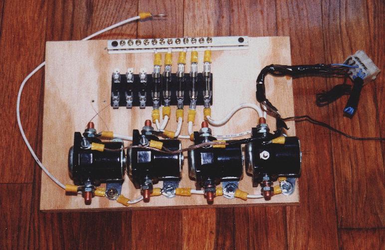
This is the relay board before it was installed in the van.
The switch box above connects to the grey connector on the right hand
side. Several of the lines in the connector wern't used, so they
were tied off.
The white wire wrapped around the left side is the ground wire, which
attached to the seat bolt.
12 volt DC power was attached to the bus bar on the top side
The devices power cables are attached to the bolts on the bolts coming
out the bottom side of the relays
here is a schematic for the whole system:
